Adjustable Trade Lock Jig Instructions
To use the B W Lockjig you will need:
- A plunge router
- 12mm long reach cutter
- 16mm guide bush and a 4mm spacer
Or - 17mm guide bush and a 5mm spacer
- A wedge or some type of door clamping device to hold the door in place while using the B W Lockjig.
- Hand Tools
INTENDED USE
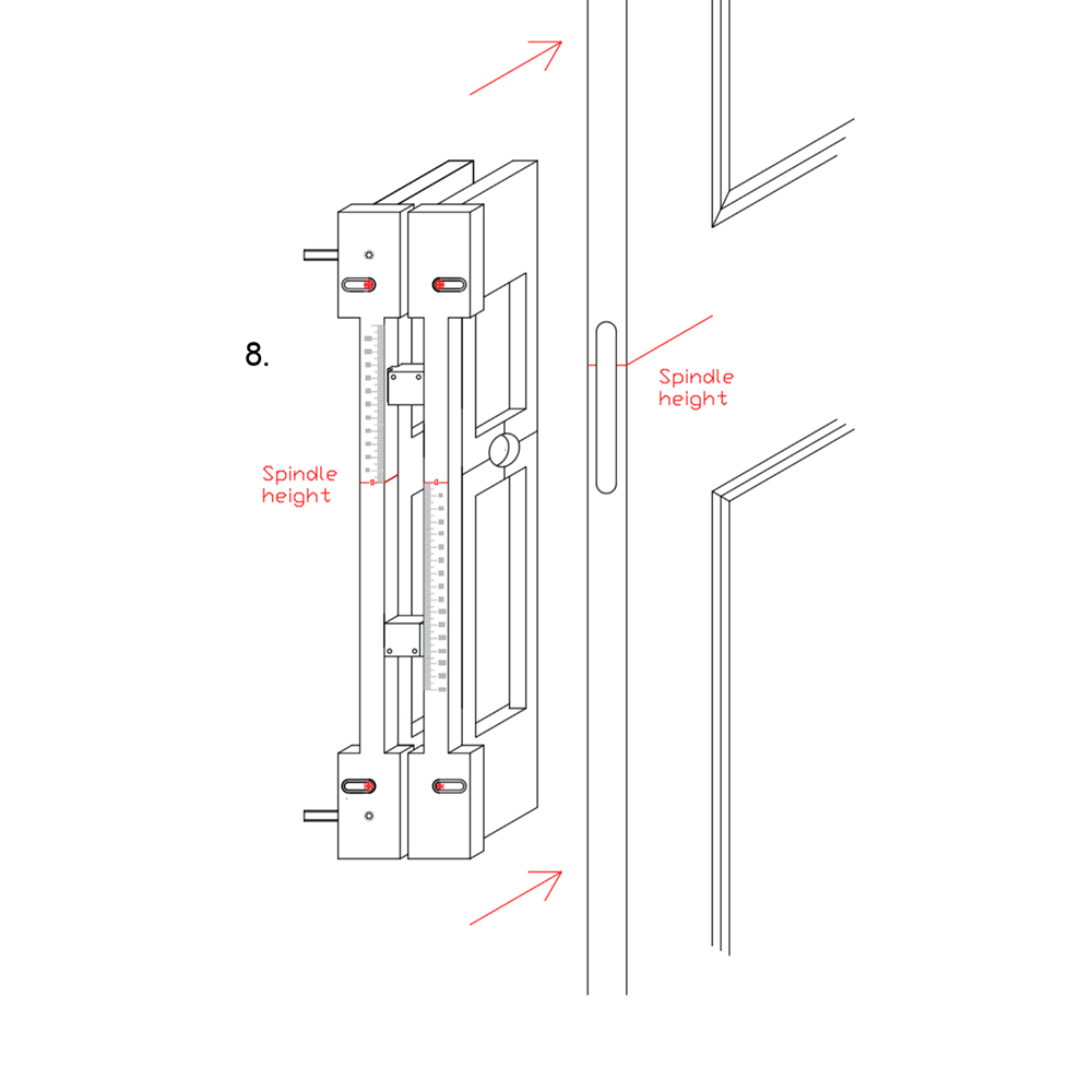
This adjustable trade lock jig is intended to be used with a plunge router with a suitable guide bush and router cutter selected and fitted to rout the spindle hole, the selected keyhole type aperture and the faceplate. The B W Lockjig is placed on the door at the given spindle height and then tightened. A self centring drill bit guide with a sleeve width of 6mm can be used to mark for the bolt through holes. (Warning, using a regular drill bit will over time increase the bolt through hole size and damage the side plates.)
SAFETY
Please take the time to read and understand the B W Lockjig safety instructions, and the power tool instructions, before use.
- Keep these instructions in a safe place.
- Users in the UK must pay attention to the Provision and Use of Work Equipment Regulations 1998, and any subsequent amendments.
- The user should also read the HSE/HSC Safe Use of Woodworking Machinery Approved Code of Practice and Guidance Document and any amendments.
- The user of this product must be competent in using wood working tools and equipment.
- All users must be competent in using woodworking tools before using this product.
- The user must consider the working environment before working with tools.
- Make sure the door is held in place securely with a wedge or a clamping device, and that the working area is clear of obstructions. Also make sure that the user is in a comfortable position before use.
- Please keep children/visitors clear from tools and the working area. Power tools come with a certain amount of risk so the operator must proceed with caution.
Tools used must meet EN847-1/2 safety standard and any amendments.
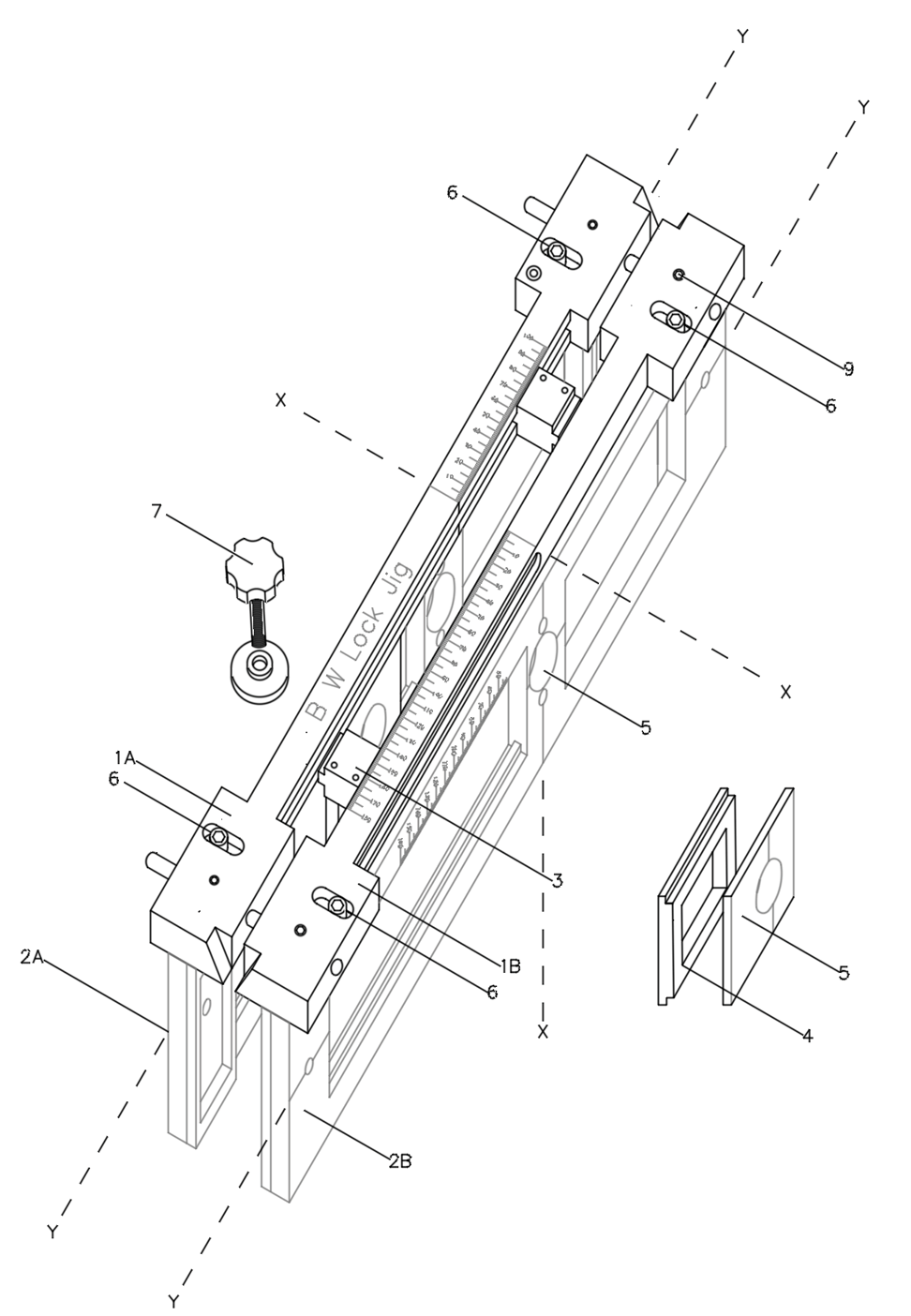
Jig Parts
- 1A Face plate left side
- 1B Face plate right side
- 2A Side plate left side
- 2B Side plate right side
- 3. Stop end
- 4. Key hole backing plate
- 5. Key hole type
- 6. Side plate screw
- 7. Star knob & thrust pad
- 8. Faceplate screw
- 9. Fixed screw
- X. Spindle line
- Y. Backset line
